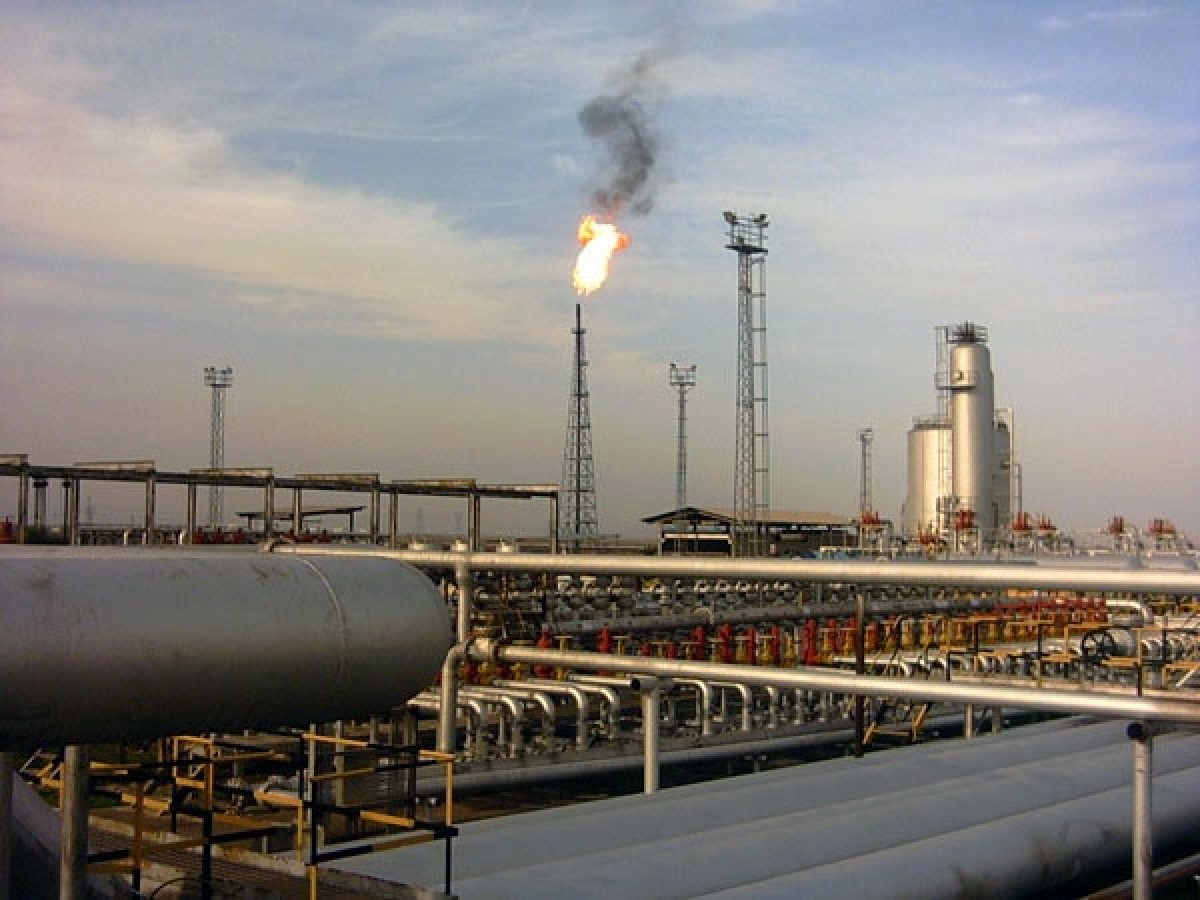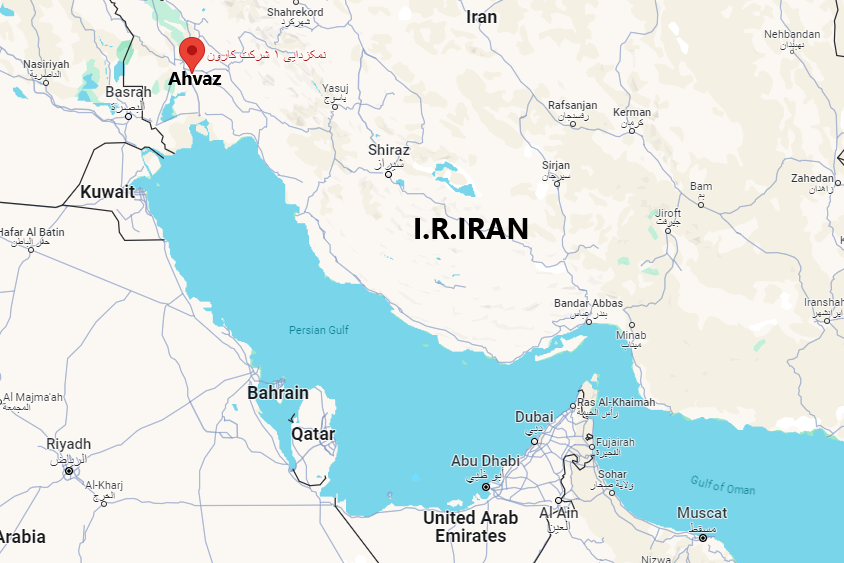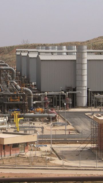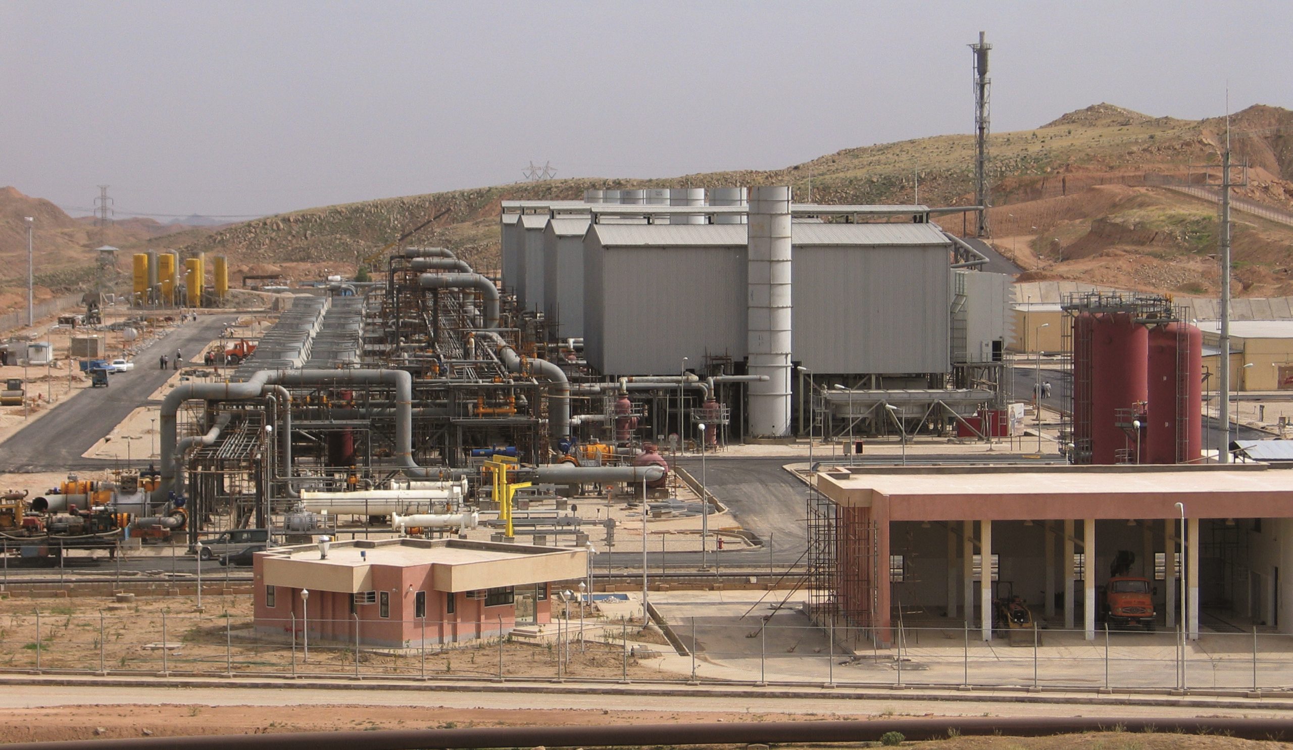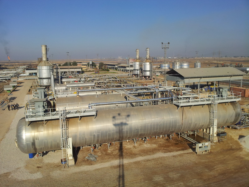
The Ahvaz-Bangestan Oil Desalting Plant Project was held in Khuzestan Province by Hirbodan Company in 2010, recommended by National Iranian South Oil Fields Company (NISOC) in the form of EPCC contract.
Scope of Services
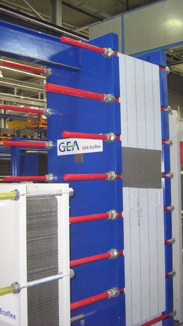
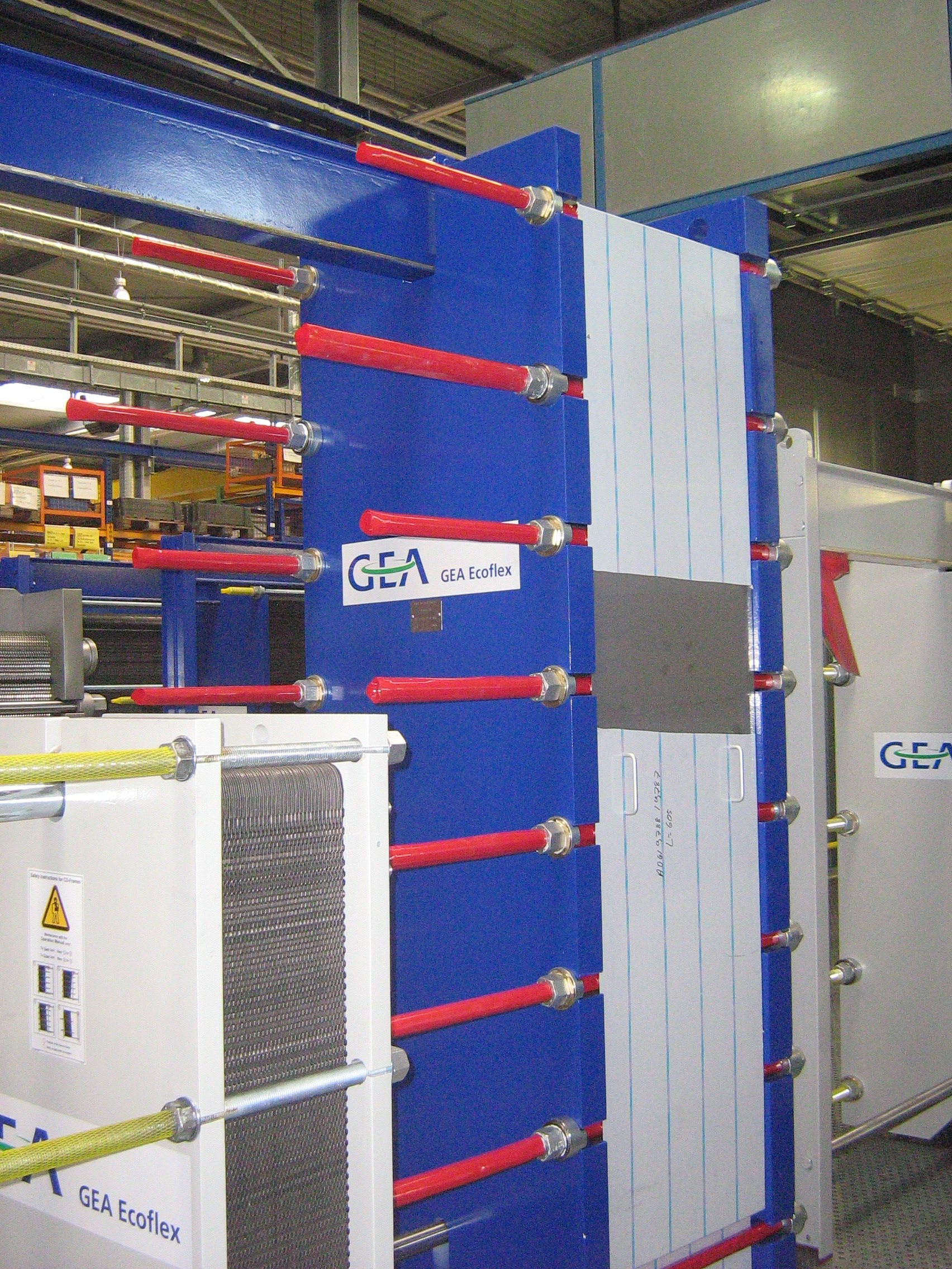
- 2 Plate Heat Exchangers
- 2 Indirect Fired Crude Oil Preheaters
- 2 Desalter/Desalted Packages
- Wastewater Treatment (IGF)
- Chemical Injection Package
- Distributed Control System (DCS)
- Emergency Shutdown System (ESD)
- Switchgear Room
Bangestsan Reservoir of Ahvaz Oilfield
Bangestsan Reservoir of Ahvaz Oilfield is approximately located at the depth of 3000m below sea level. Ilam and Sarook geo formations of this reservoir include considerable amount of hydrocarbory content. This reservoir was explored in 1958 and its operation was commenced in 1971. The capacity of this reservoir at its first oil level is estimated of about 37.28 billion barrels. / Wikipedia.org
Project Nature
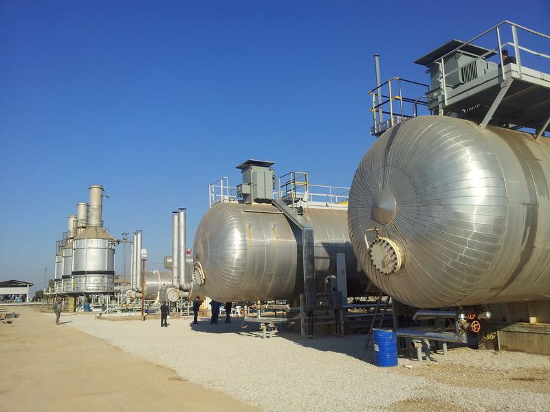
The nominal capacity of Ahvaz-Bangestan desalting unit is 110,000 b/d. Due to this region’s special crude oil properties such as high density and viscosity, micron sized water molecules, being rich in minerals, wax and asphaltine combinations, current oil refining facilities do not possess the ideal efficiency.
The purpose of this project is to develop the existing desalting plant to increase the desalting capacity of Ahvaz-Bangestan (unit 1). To do this, a new desalting train with capacity of 55,000 b/d (Dry Basis) including 10% BS&W (basic sediment and water) is considered. The new desalting train includes: Crude/Crude Heat Exchanger, Indirect Fired Heater, and Double Stage Electrostatic Desalter.
Studies on this region’s crude oil show that as a result of containing stabilizing material such as asphaltine and also Bangestan wells’ low water levels, strong salty emulsions emerge in it which grow and gain more stability with pressure drops in time. Also as oil is passing through near-ground facilities, salt crystals might form as well because of the lack of underground water reservoir.
Project Goals
What the project is seeking to bring into existence falls on some key targets as follows:
- To reach desalting to the amount of 29 g/m2 and dehydration to the amount of 0.15 wt%.
- Na2S (Sodium Sulphide) injection amount to the inlet effluent water for the purpose of free oxygen reduction, is 21 lit/day.
Project Units Details
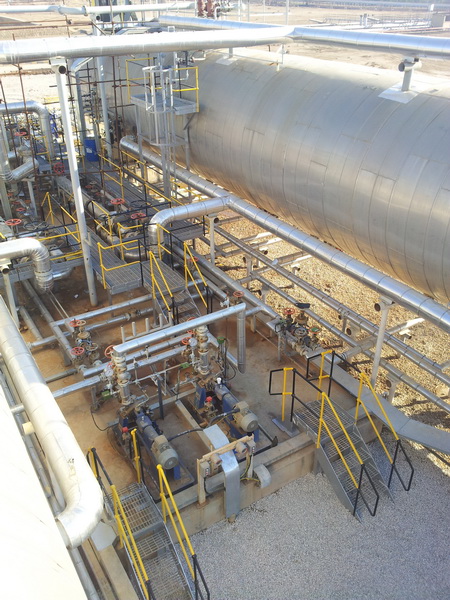
To improve the efficiency of existing desalting plant, two plate and frame heat exchangers are suggested for crude and water lines to warm up the inlet crude and inlet dilution water streams with desalted outlet crude and water return, respectively.
For heating recovery and optimization, a plate and frame heat exchanger have been suggested at desalting package inlet. The exchanger contains two crude streams:
- The product stream from desalter outlet (hot side)
- The feed stream from booster pumps that should be transferred to preheaters (cold side).
Stream of Procedures
The outlet stream of plate and frame heat exchangers are heated up to 65˚C by passing through two parallel sets of indirect fired heaters. Normally, two desalters work in series but working in parallel is also possible. The salty crude enters into the first stage of desalter and after being processed in this step, the crude is transferred to the second stage by pressure difference.
The dilution water enters to the second stage after passing through a plate and frame heat exchanger and transferring heat with exiting oily water. To add water to crude, a mixing valve is considered. After processing in the second stage, the concentrated water transfers into the first stage desalter by circulating pumps.

The outlet stream of existing desalting package is treated by passing through a skimmer tank and API separators and as its consequence, the oil content decreases to 200ppm. After startup of new desalting plant, both outlet water streams, similarly, enter skimmer tank and API separator. In this projectو the oil content shall be decreased down up to 25ppm using an Induced Gas Flotation (IGF) package.

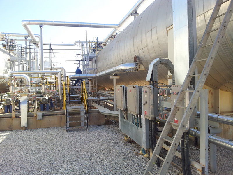
Other auxiliary equipment includes: A) Closed drainage system, B) Compressed air supply system, C) Emergency diesel-generator fuel supply system, D) Surface water treatment system, E) Torch, F) Pit burner system, G) Tanks, and H) Pumps already manufactured for the capacity of 110,000 b/d.
Upgarads Ahead
Other upgrades are as follows:
- Installation of mixing valves downstream of desalters and injection of effluent water prior to these valves.
- Design and installation of plate and frame heat exchangers before pre-heaters for direct heat exchange between inlet crude oil and outlet desalted oil. This method not only provides the ideal process temperature and helps save energy but also prevents oil dissipation.
- Design and installation of water/water heat exchangers to increase temperature of injected water to desalters and coalescer tank.
- Installation of IGF and Nut shell filter to improve the quality of wastewater
- Firefighting system